Codam light
Published @ 08-07-2024
— “Red means DON’T ENTER!”
The project was originally Daoyi’s idea, my contributions are the electronics and some parts of the code.
the plan was to build a light for each of the auditorium doors that change colours to show what is happening inside, plus a smaller light inside auditorium to act as visual feedback.
The lights are controlled with a single remote over radio communication.
Electronics
Remote
The remote has 4 buttons each corresponding to a different light color, each button is hooked up to a interrupt pin. It is built around a barebones ATmega328p chip running on its internal oscillator at 8Mhz. The main design constraint for the remote was making it energy efficient, so it could run off a coin cell battery.
Internal oscillator
We’re running it off of its internal oscillator to reduce part count and save some power. To get to set this up we had to flash a different bootloader, mainly because it seemed easier than setting the fuses by hand.
We used 2 Arduino Uno’s one as a programmer loaded with this sketch, and another as the target device, aka the chip that will be in the remote.
This post explains how to set it up.
Reducing current consumption
This site has a lot of information on the topic.
- Processor always sleeping only waking up on interrupts.
- Turn off the Watchdog timer (WDT).
- Turn off the brown out detector (BOD).
- Setting unused pins as output.
- Because of the coincell the supply voltage is around 3V which would probably reduce the clock frequency
Applying these tricks we got the consumption down to around 2.6uA while sleeping, now I’m not sure how accurate this number is since I’ve only measured it with one multimeter.
But say the battery has 210mAh and we’re drawing 2.6uA that would put us at around 9 years, so pretty good :)
[TBA PIC OF REMOTE]
Light
Light strips
The lights are 24V-RBGW led strips, they are driven by a 4 channel mosfet board, which is controlled by an Arduino Pro Micro. All being powered by a 24V LED powersupply, which needed some tricks to get working.
Controller board
The 24V supply feeds into a buck-converter generating the board’s 5V rail.
It features a RF24 radio module, with an 3v3 LDO adapter board to so it can run off of the 5V rail provided by the buck-converter.
We went with the RF24 after some experimentation with other radio modules, mainly because it has some ✨ TCP acknowledgement ✨ thing going on, improving the reliability of the system. It uses SPI allowing you to configure some more settings compared to a simple 4 button garage door type radio.
Inrush current
The 24V LED supply could not handle the (pretty small) inrush-current the buck-converter had, so after experimentation I added a inductor in series between the buck-converter and the 24V supply, which fixed the issue.
I found this fix when swapping out different 24V power supplies and noticing that with a longer wire between the power supply and the buck-converter it would work, but not if I used a smaller wire.
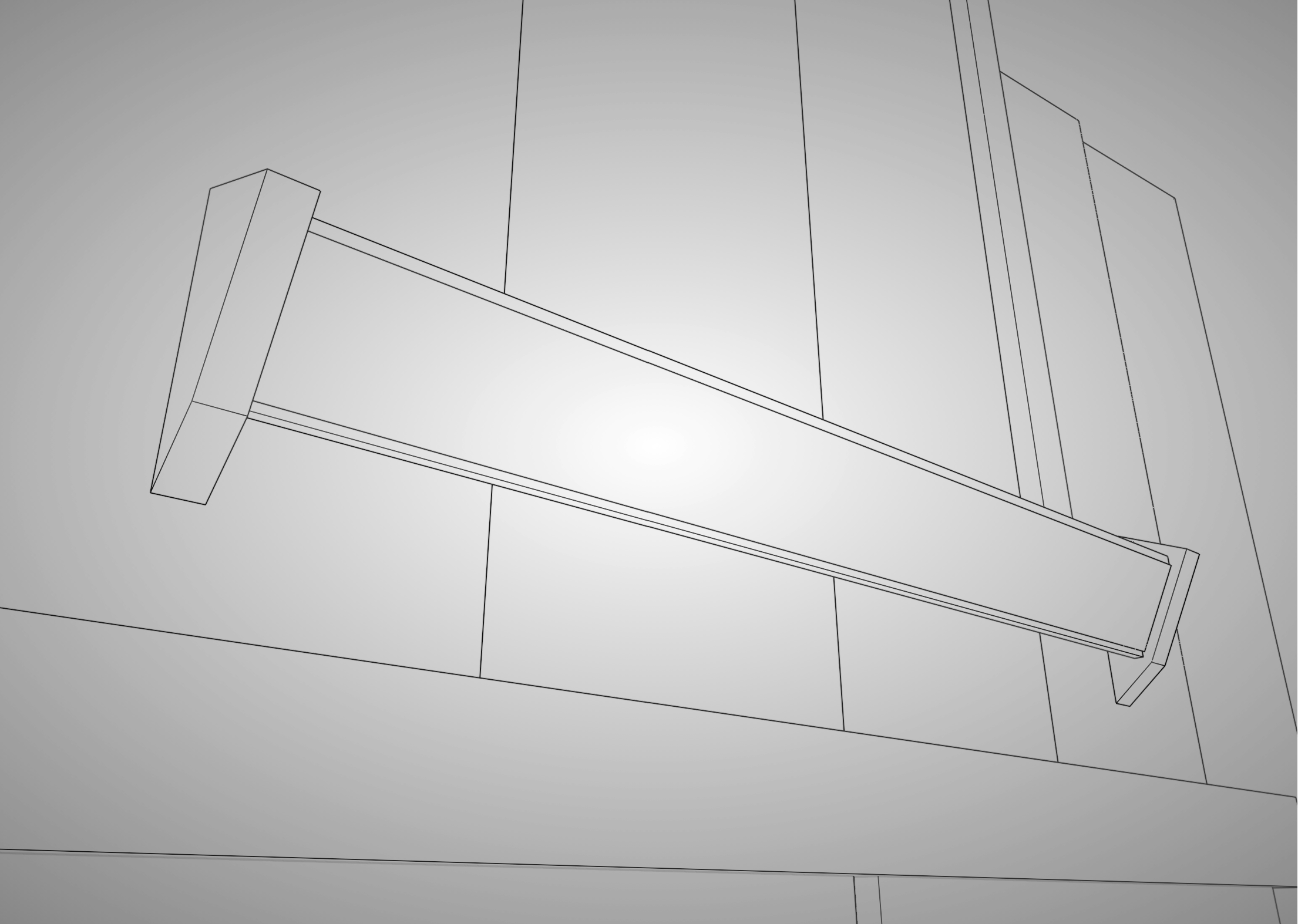
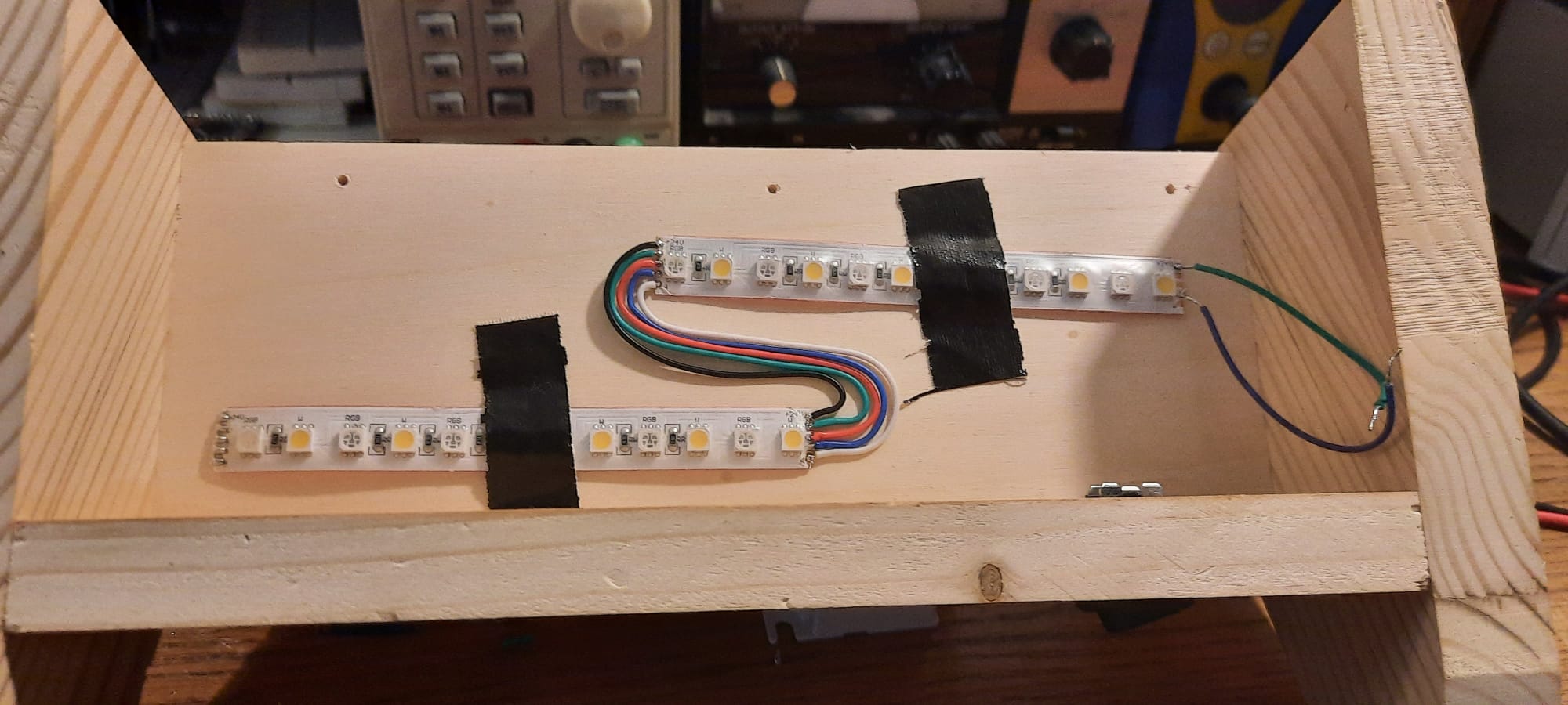
Insides of small light (the tape was temporary)
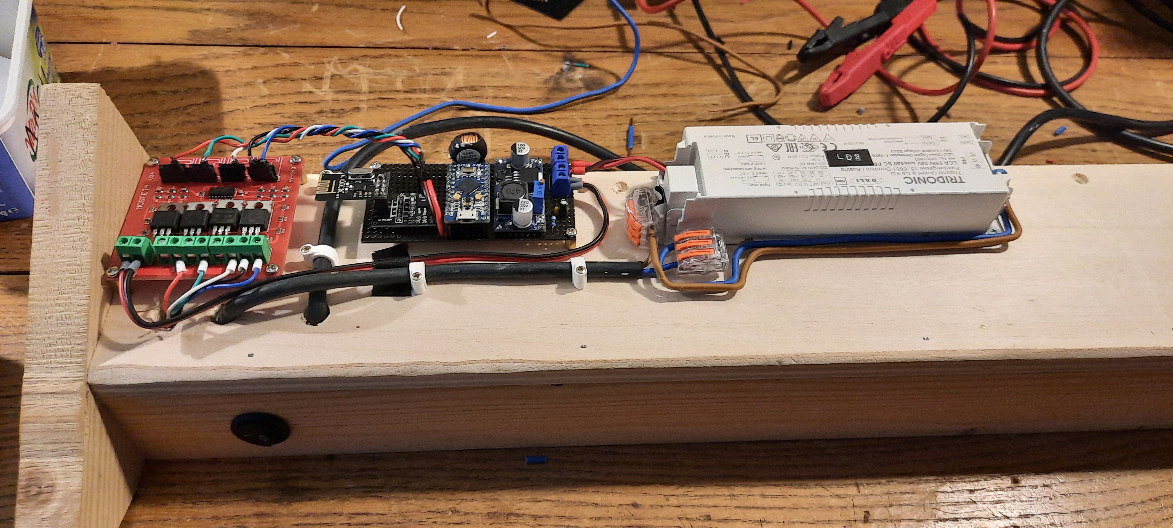
Back assembly of a large light
Software
You can checkout the software repo over here.
Payload
The thing both the Light and Remote have in common is the ✨ Payload ✨, this payload has a few things to it.
It is essentially a 1 byte word being used as bit-fields, where the 4 MSB each correspond to one of the four buttons on the remote.
The 4 LSB correspond to the address of each light, when the remote sends a payload these fields are cleared. Say light LD1 receives the payload: It will set its own bit-field and foward it to the other lights that don’t have their field set.
This is super dirty way to make a “mesh” network, it also adds a bit more redundancy incase a light is out of range of the remote, but still in reach of another light.
Remote
We used 2 wrapper libraries to handle interfacing with the ATmega’s registers.
The code for the remote can be boiled down to the following steps.
- Setup the RF24 over SPI.
- Setup
pinChangeInterrupt()on the button pins. - Call
LowPower.powerDown()to sleep forever until we hit an interrupt. - When an interrupt fires it will wake up the CPU and will store the pin which triggered the interrupt.
- When the CPU is running it will call
radioSend()with the saved button, which will generate thepayloadand send it. - After that it will hit another
LowPower.powerDown()and the whole cycle repeats.
Light
This part is very simple. The light will poll the radio for the incomming payload, when it receives anything it will foward it to the lights that have not received this payload yet. After that it will set the 4 PWM channels to the corresponding color.
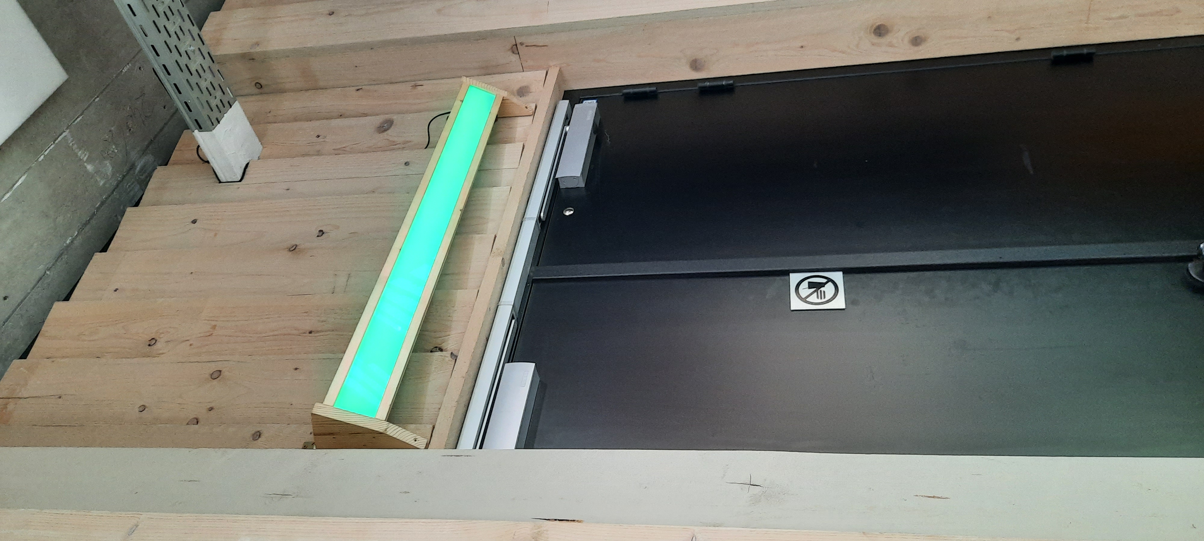
Final results
Resources
Nick Gammon has a great forum filled with tons of knowledge which helped a lot.